Facade Panels & Anchor Slotting
For numbered facade panels, concealed fixings and full-height corner returns.
- Materials
- Stone or compatible slabs approved for the project fixing and machining details.
- Process
- Size the panels, cut the approved anchor grooves and bevel straight mating faces where a mitred return is specified.

Recommended setup
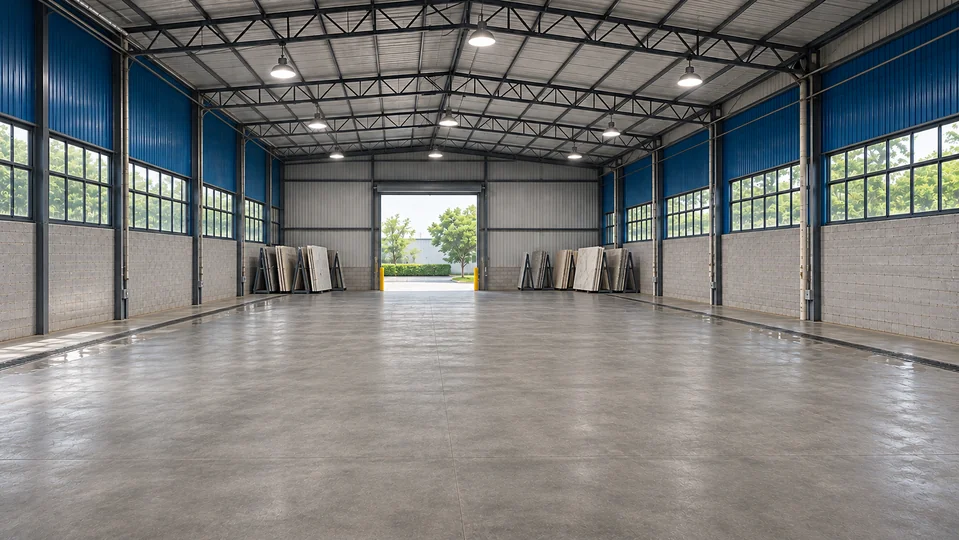
Setup 01 matches the workshop image above. Compare other setups for different parts or processes.
Setup 01
Double-blade bridge saw + anchor slotter + rail beveler
Size facade panels, machine the specified anchor grooves and prepare long mating bevels on the panels with mitred returns.
Workflow
- Size and mark panels
- Machine specified anchor slots
- Bevel required returns and test anchor and corner fit
-
Three-Axis Double-Blade CNC Bridge Saw
Size panels using a blade pair selected for the material.
- Output
- Sized panels with a marked reference edge.
- Overall size
- 4800 × 3050 × 2400 mm
-
1800 Automatic Anchor Slotting Machine
Machine specified figure-8 or L-shaped anchor grooves from the panel datum.
- Output
- Panels with slots ready for anchor-fit inspection.
- Overall size
- 3200 × 1500 × 1750 mm
-
3200 Precision 45° Beveling Machine
Machine long straight 45° mating faces on supported panels.
- Output
- Protected bevel faces for dry fitting.
- Overall size
- 5000 × 1450 × 1500 mm
Compare other setups
Setup 02
Double-blade bridge saw + anchor slotter
For numbered panels with a project-specific anchor groove.
Workflow
- Size and establish the datum
- Cut specified anchor slots
- Check fit with the actual anchor
-
Three-Axis Double-Blade CNC Bridge Saw
Size panels using a blade pair selected for the material.
- Output
- Sized panels with a marked reference edge.
- Overall size
- 4800 × 3050 × 2400 mm
-
1800 Automatic Anchor Slotting Machine
Machine specified figure-8 or L-shaped anchor grooves from the panel datum.
- Output
- Panels with slots ready for anchor-fit inspection.
- Overall size
- 3200 × 1500 × 1750 mm
Setup 03
Bridge saw + double-edge slotter
For compatible repeated slots on both edges after qualification against the fixing drawing.
Workflow
- Size and mark blanks
- Machine both compatible edges
- Measure slots and record panel IDs
-
Three-Axis Double-Blade CNC Bridge Saw
Size panels using a blade pair selected for the material.
- Output
- Sized panels with a marked reference edge.
- Overall size
- 4800 × 3050 × 2400 mm
-
1200 Six-Head Double-Edge Slotter
Cut compatible repeat slots on both edges of a supported panel.
- Output
- Panels with matched fixing grooves.
- Overall size
- 2800 × 2200 × 1600 mm
Finished parts in use
Check concealed anchor fit at the sample stage, then inspect the installed joint grid and corner returns. Applications are shown for illustration.
Anchor slots and fitting checks
-

Concealed slot sample Measure the cut from the panel datum. Confirm the approved anchor profile and the remaining stone thickness. -

Anchor seated in the sample slot Check how the approved hardware seats against the slot drawing before releasing the batch. -

Sample panel with a slot and chamfer Check the slot and visible chamfer against the drawing on the same full-thickness sample. -
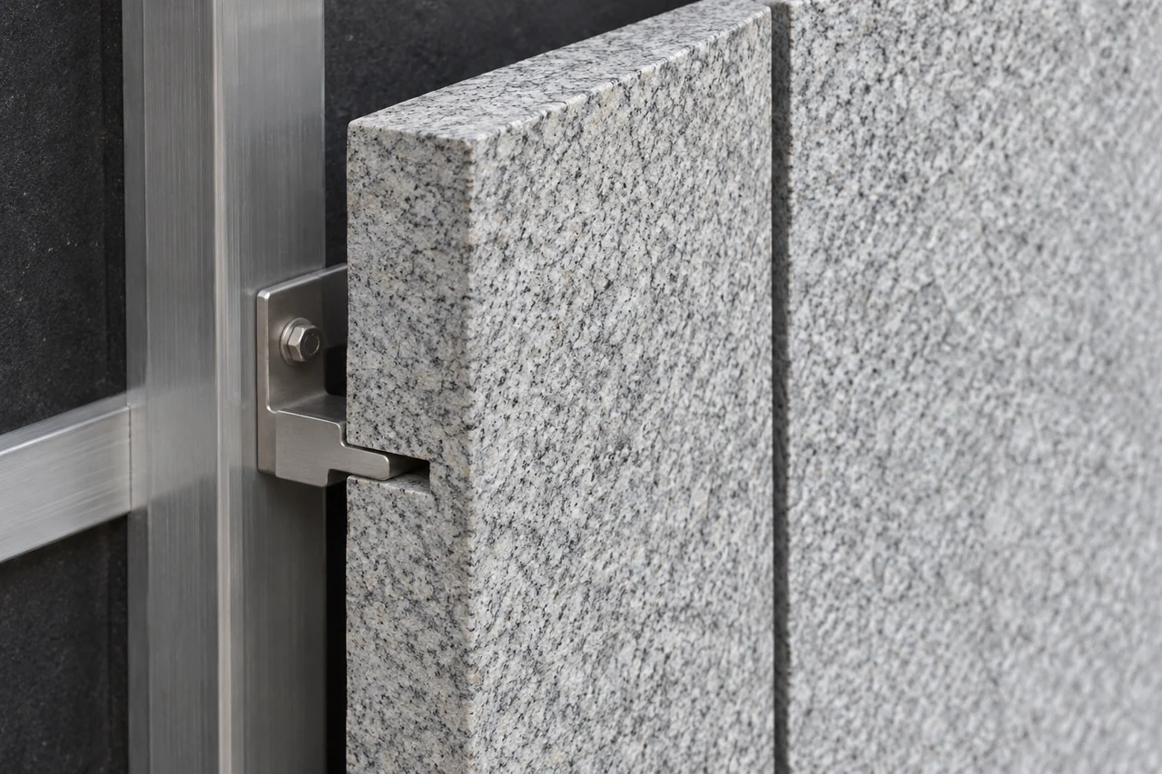
Panel slot and bracket in section Test bracket seating and verify the remaining stone thickness using the approved hardware.
Facade panels, openings and returns
-

Facade panel in use Keep each panel traceable to its fixing drawing and installation position. -
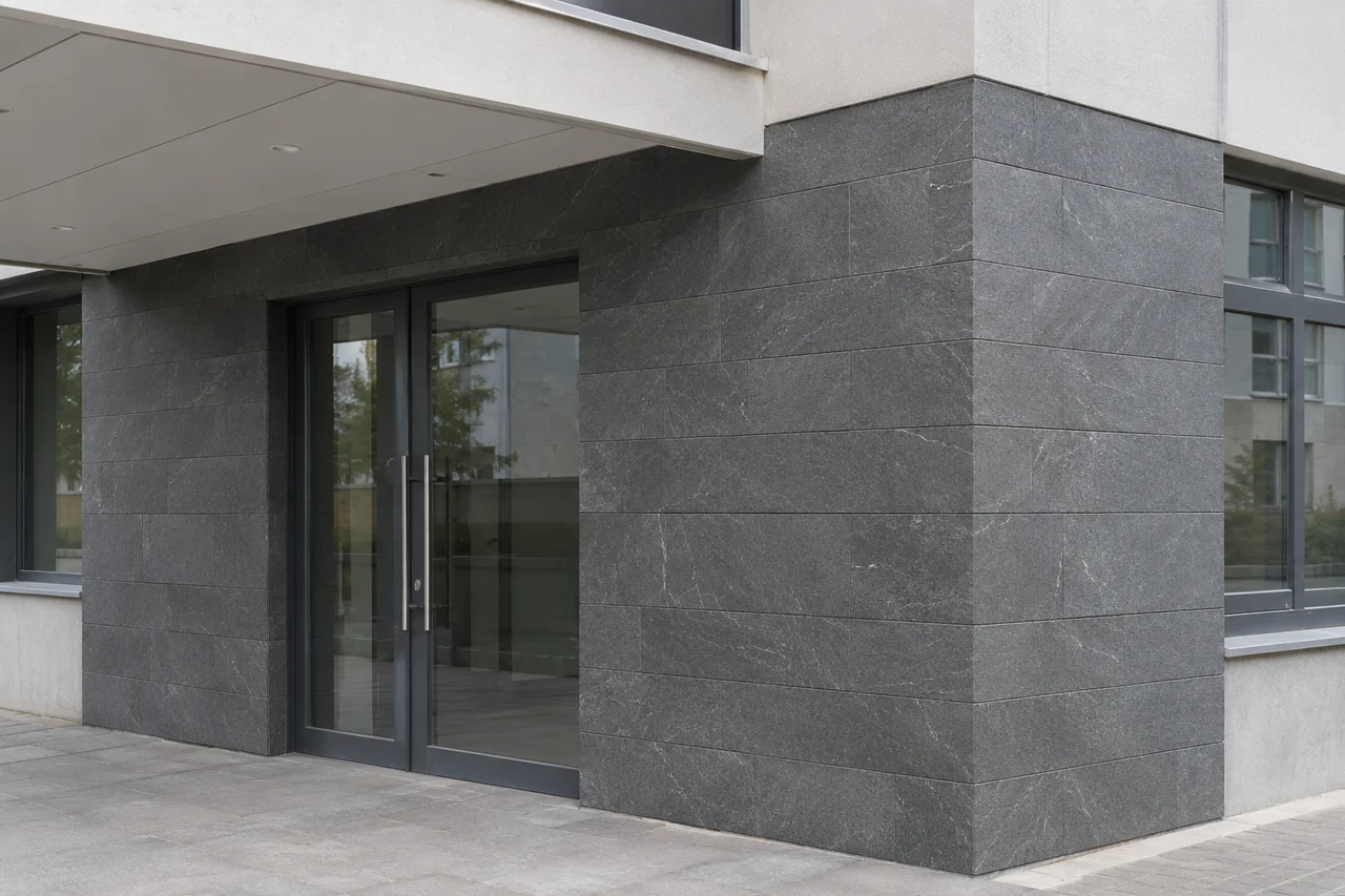
External cladding return Check the vertical corner seam and the alignment of the courses around the return. -

Cut-to-size entry surround Dry-lay the head and side panels in installation order to check the joints around the opening. -

Stone panels at a recessed entry Check the face-to-soffit joint and panel fit against the approved fixing detail.
Check the fit for your workshop
Check your drawings against machine limits, then plan how slabs and finished parts will move through the workshop.
Part requirements
Mark the panel ID and visible face. Carry the fixing datum into slotting and keep each mitred return paired with its matching panel.
Panel schedule
Match every panel to the visible face, datum and installation sequence.
Anchor geometry
Provide slot type, position and remaining material from the approved fixing drawing.
Corner details
Mark the mated edges and return depth, then check a full-size joint.
Single-machine operations and model details
 Machine details
Three-Axis Double-Blade CNC Bridge Saw
- Functions
- Size panels using a blade pair selected for the material.
- Core configuration
- Three-axis CNC movement and double-blade cutting head. Qualify blade setup and visible-edge quality on the actual slab.
 Machine details
1800 Automatic Anchor Slotting Machine
- Functions
- Machine specified figure-8 or L-shaped anchor grooves from the panel datum.
- Core configuration
- Automatic lift slotting head. Catalogue processing width is 100–1800 mm and thickness is 6–30 mm.
 Machine details
3200 Precision 45° Beveling Machine
- Functions
- Machine long straight 45° mating faces on supported panels.
- Core configuration
- Rail-type 3200 model. Catalogue thickness is 5.5–30 mm. Verify support over the entire part and remaining face material.
 Machine details
1200 Six-Head Double-Edge Slotter
- Functions
- Cut compatible repeat slots on both edges of a supported panel.
- Core configuration
- Six-head double-edge configuration. Catalogue width is 250–1200 mm and thickness is 6–50 mm.
Workshop layout and handling
The estimate adds the footprints of the machines in Setup 01. Allow extra room for loading, aisles, servicing and auxiliary equipment. Confirm the installed layout for your site.
- Long-panel supports
- Plan racks and turning space for the largest pieces.
- Slot inspection station
- Set aside a bench with the actual anchors and the current fixing drawings.
- Protected packing
- Keep chamfers, corners and numbered batches protected in installation order.
Technical answers
Before you order
Review machine fit and sample checks, then see what to send for an equipment quote.
Discuss your setupWhich anchor slot can the 1800 machine produce?
Match the approved anchor and groove drawing to the machine’s slotting configuration. Trial the slot position and remaining stone with the actual hardware.
Which panels use the precision beveler?
Route panels with specified long 45° mating faces to the beveler. Confirm full-length support and approve a complete dry-fitted pair.
What should I record from the trial?
Trial the approved anchor in a full-thickness panel. For mitred returns, dry-fit a full-length pair. Record slot location and joint-face alignment. See the finished-part checks.
What do you need for a quote?
Send the panel schedule, material, size range, approved fixing drawing and anchor sample. Include the longest mitred return and required quantities.
