Production line
planning

Plan the right equipment sequence for your workshop.

Match loading, cutting and finishing stations to your part sizes, edge requirements and batch mix. Set the equipment order and define how parts are supported and transferred between machines.

For a new line or an upgrade, review connections to existing equipment, operator access and the space needed for loading material and collecting finished parts.

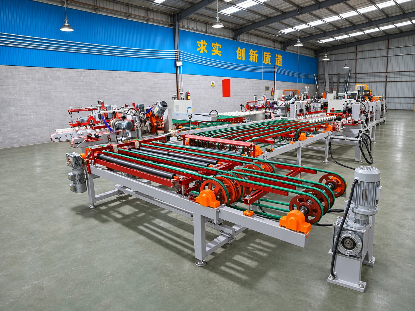
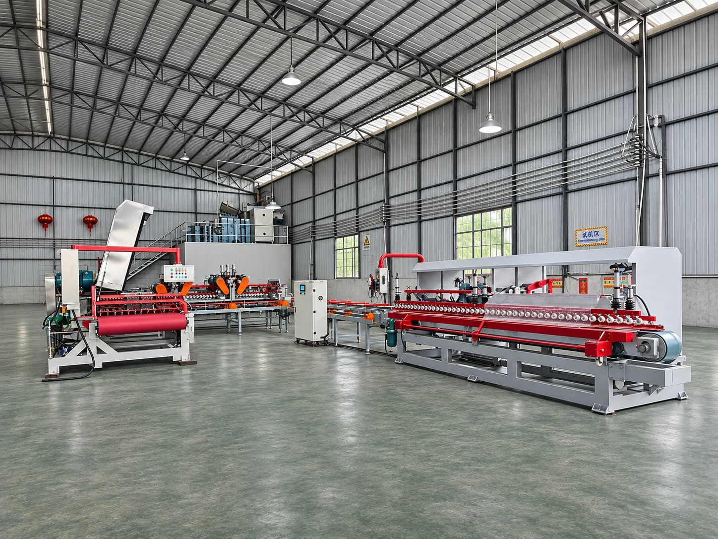
Ground-level view of the cutting and edge-processing line with its transfer conveyor

Production line concepts

Choose a route by the operations your parts need.

Automatic loading & cuttingFor repeated batches of cut-to-size tile or slab parts.
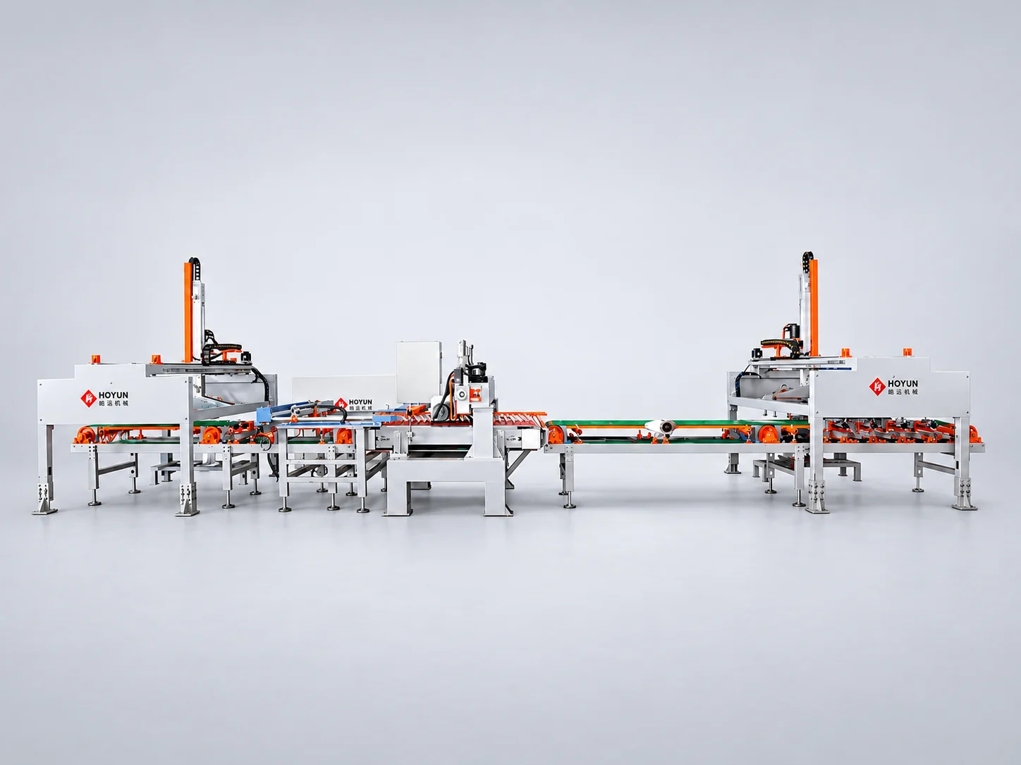
Concept layout for automatic loading, unloading and cutting
Material & batch
List the incoming formats, thicknesses and finished sizes for each cutting pattern. Include batch quantities and the format changes expected during a normal shift.
Loading & collection access
Show where incoming stacks are replenished and finished parts are collected. Allow access at both ends without crossing the material route.
Part support & changeovers
Identify the smallest finished part and its support during discharge. Confirm the locating and handling adjustments needed when switching between formats.
  1. Load & locate

    Present the incoming stack and establish the reference for cutting.

  2. Cut to size

    Follow the agreed cutting pattern with the material supported through the cut.

  3. Unload & collect

    Support cut parts as they leave the cutting station and enter collection.

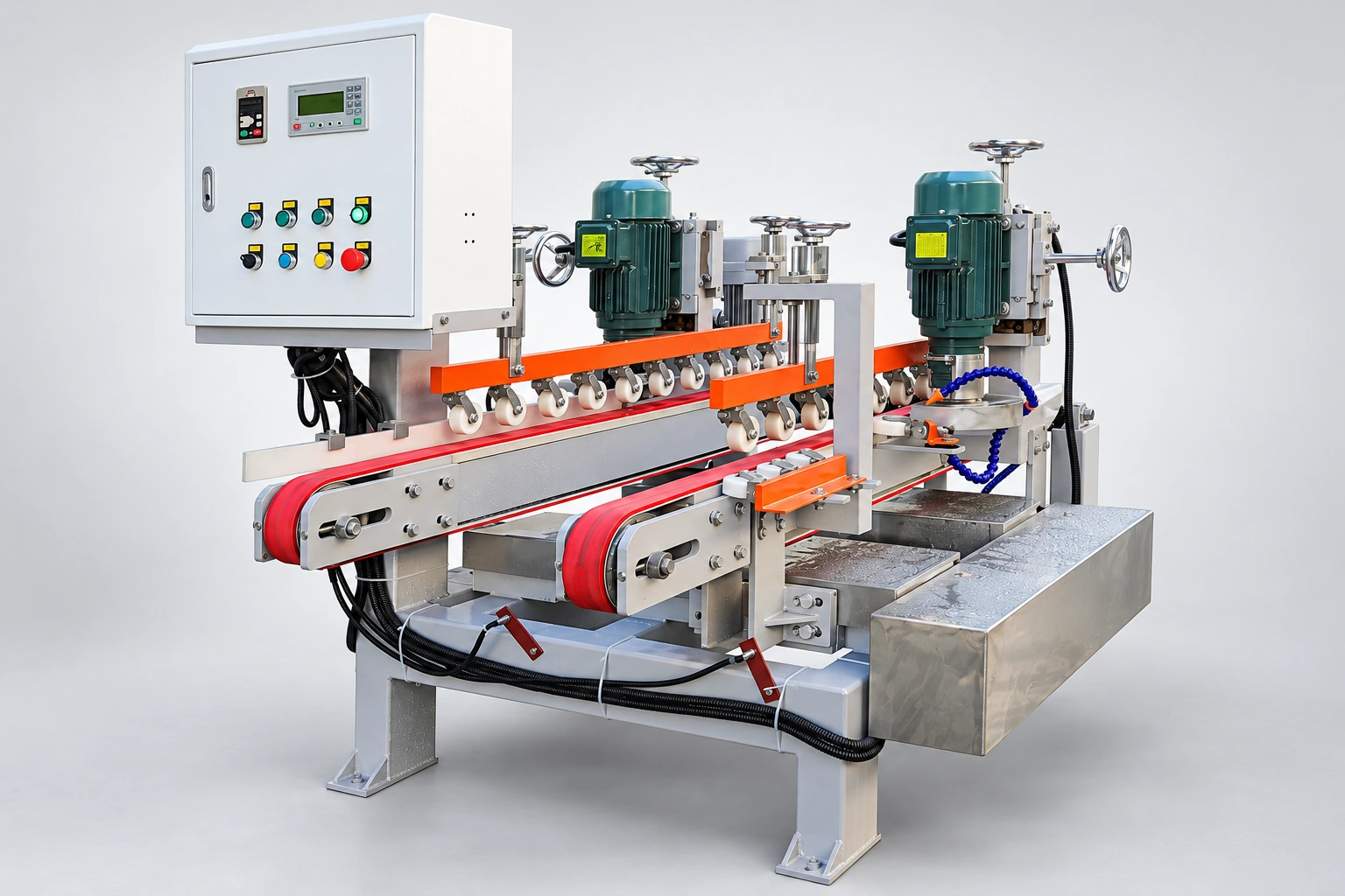
Concept layout for cutting and edge grinding
Cutting allowance
Agree the stock left after cutting so grinding can reach the finished dimensions. Include the incoming size, target size and edges that require processing.
Edge finish
Mark the edges to process and provide a finish sample. Use it to review the tool sequence and the condition expected before collection.
Transfer & orientation
Show the reference edge and feed direction at the handover to grinding. Check support for the smallest format and clearance for the finished edges.
  1. Cut to size

    Prepare the cutting pattern from the incoming format.

  2. Transfer & orient

    Support the part as it enters grinding and establish the locating edge.

  3. Grind the edges

    Process the specified edges, then discharge the part into collection or the next operation.

Concept layout for double-side slotting
Groove drawing
Provide section drawings showing groove positions, depths and reference faces on both sides. Include the incoming and finished part dimensions for the locating review.
Second-side setup
Confirm how the part is presented and located for the second side. Check whether reorientation is required and allow access for tool adjustment.
Sample & inspection
Use a representative part to review groove position, depth and the condition of the surrounding surface. Agree where inspection and collection fit into the route.
  1. Feed & locate

    Present the reference face and edge to the initial feed direction.

  2. Process the grooves

    Keep the part located while machining the specified sides.

  3. Transfer & check

    Reorient where required, inspect the grooves and collect completed parts.

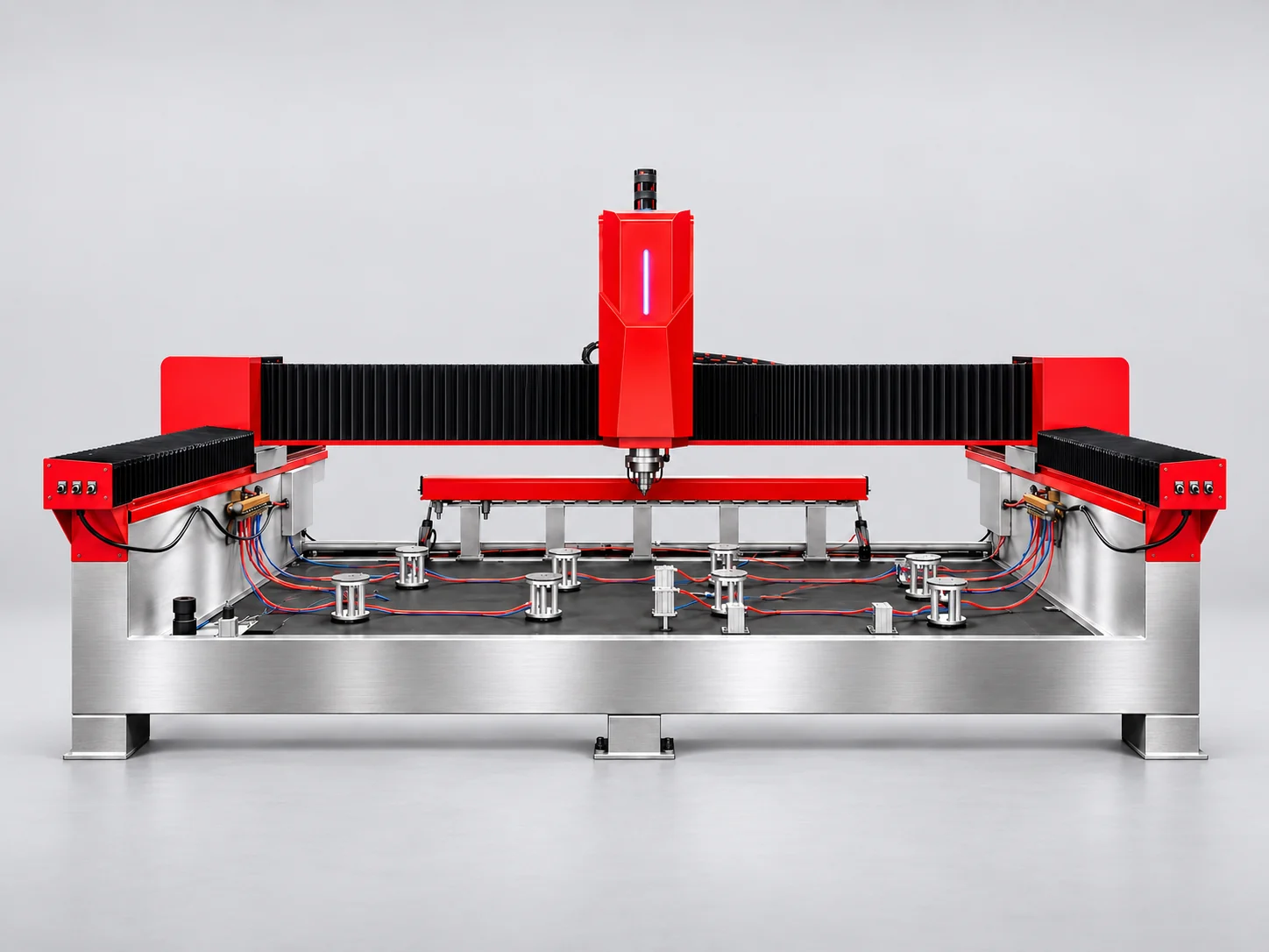
Concept layout for automatic kitchen countertop production
Drawing details
Mark outlines, sink openings, joints and visible edges on the drawings. Include narrow sections that need support when parts are moved between operations.
Material & handling
Provide slab material, size and thickness, plus loading access and collection positions. Check how cut-outs and finished edges will be supported during lifting and reorientation.
Station sequence
Assign each operation to a station before setting the transfer route. Review workload across the part mix, including changes between countertop layouts.
  1. Slab input

    Load and locate the slab using the cutting reference.

  2. Cut & machine

    Assign outline cuts, openings and edge work to the proposed stations.

  3. Transfer & collect

    Support openings and narrow sections during reorientation and collection.

Factory line examples

Cutting & edge processing

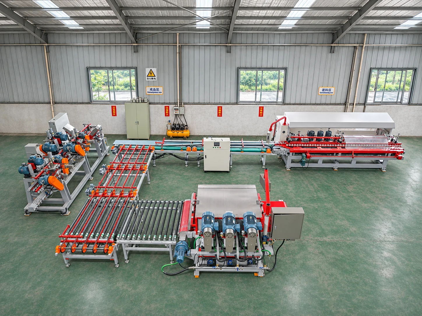
Cutting and edge-processing stations linked by conveyor transfer produce sized parts with processed edges.

Dimensions & edge finish
Provide finished dimensions, edges to process and a finish sample. Agree the cutting allowance for the final edge operation.
Station handover
Review conveyor height, part support and orientation through each direction change.
Operation & access
Define the control connections, collection area and access for tooling and maintenance.
Process flow

  1. Cut to formatPrepare the part with the allowance required for edge work.
  2. Transfer & locateSupport the cut part and establish the next locating reference.
  3. Process the edgesMatch the edge operations and tool sequence to the finish sample.
  4. Collect & checkCheck the finished format and arrange supported collection.
Loading, cutting & edge processing

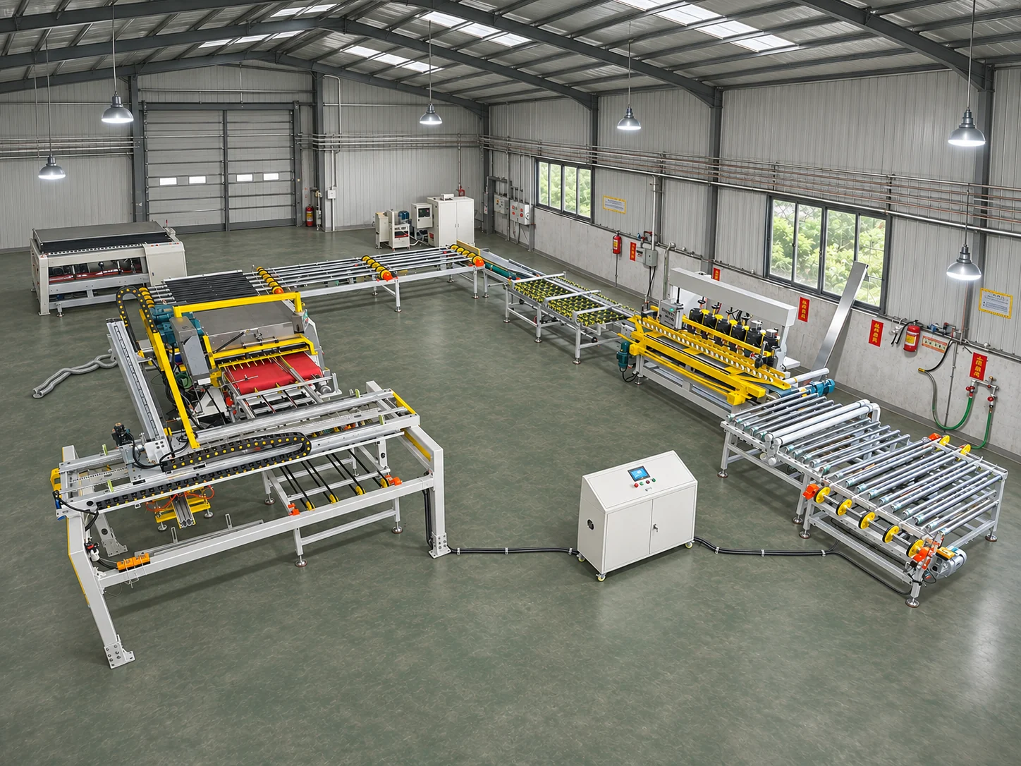
Loading, cutting and edge-processing stations form one route from incoming stock to cut-to-size parts with finished edges.

Incoming material
Provide stock sizes, thickness, stack presentation and access for replenishing the loading area.
Part mix & transfer
Provide finished-part drawings and the cutting pattern for each batch. Review size changes and the handover into edge processing.
Collection & services
Reserve space for completed parts, operator access and the required site connections.

Process flow

  1. Load & locatePresent the incoming material and establish its cutting reference.
  2. Cut to sizePrepare the required formats from the agreed cutting pattern.
  3. Transfer & finishLocate and support the parts as they enter edge processing.
  4. Discharge & collectPlan how finished parts leave the line and are collected.

Four-side grooving

Grooving stations linked by rollers and cross-transfer belts process the four sides of a component.

Groove geometry
Mark groove positions, depths, reference faces and inspection points on a section drawing.
Direction change
Review cross-transfer, locating and part support between the first and remaining groove operations.
Tooling & discharge
Agree access for tool adjustment, inspection and collection without obstructing the transfer route.

Process flow

  1. Feed & locateEstablish the reference face and the first feed direction.
  2. Groove the first sidesAssign the initial groove operations from the part drawing.
  3. Cross-transfer & locatePresent the remaining sides with the required support and reference.
  4. Complete & inspectFinish the remaining grooves and check their positions and section.

Prepare your project

  1. Part drawings & samples

    • Material, thickness and incoming sizes
    • Finished dimensions, groove details and reference faces
    • Edge requirements and a finish sample
  2. Production target & part mix

    • Target output and available production time
    • Part sizes, quantities and batch changes
    • Required operations for each part family
  3. Floor plan & site services

    • Floor plan with doors, columns and access routes
    • Loading, collection and maintenance space
    • Power, water and drainage connection positions
  4. Existing equipment & supply scope

    • Existing machine models, dimensions and transfer heights
    • Current material route and control interface requirements
    • New equipment and tooling, with supply and connection responsibilities

Ceramic tile processing line in operation

See conveyor transfer between the processing stations.

Workshop video

Technical answers

Before you order

Confirm equipment scope, compatibility and output before ordering.

Discuss your requirements
Are automatic loading and unloading included?

Inclusion depends on the agreed configuration. Confirm loading, unloading and transfer equipment in the equipment list and quote.

Can the line connect to my existing equipment?

Existing machines need a compatibility review before direct connection. Agree any additional transfer equipment and control work before finalising the layout.

How is line output assessed?

Review loading, processing, transfer, collection and batch changes across the full route. A single machine’s cycle time does not establish line output.

Can the line be installed in stages?

Phasing needs to be agreed before the layout is finalised. Define what each stage can run independently and reserve the access, transfer and service connections needed for later stages.

Talk to HoYun

Discuss your equipment needs

Tell us what you make. Include the material, workpiece dimensions, required processes and target output. Add the model if you have a machine in mind.

Explore all machines

Sales enquiries

Connect on WeChat

Scan this code in WeChat or add our sales number. On your phone, save the code to scan from your photos.

HoYun sales WeChat QR code

+86 156 2720 7763

Save QR code

Sales enquiries

Talk to HoYun

Connecting to live chat…

You can also reach our sales team directly.

WhatsApp +86 156 2720 7763Jessie@hoyunmachinery.com